


 54 / 100

February 2016
54
A
fter hearing many Dutch
hams on the 40 and 20 metre
band using a commercially
bought end-fed antenna, I thought
for a while, how is it possible that
such a small and strange design
can put out such a good signal?
I was very sceptical at first. I had my share of
stories on miracle expensive wonder antennas
far too often, but after hearing more and more
hams bragging about their great results they
had with this, for me a bit strange design, it
started to raise my interest.
Often this end-fed idea has certain
advantages like:
• The antenna can be placed in a few different
ways like sloping-up, sloping-down,
horizontally like any dipole, inverted-V, and
even vertical, without using any radials
• Feeding the antenna at the end (or
beginning, however you look at it) can make
it easier to reach with the coaxial cable
• You only need 1 or 2 high points to place
the antenna, unlike a centre fed dipole
where you often need 3 high points to get it
up in the air in a good way
• The antenna is fairly easy to build for use
on 3, 4 or even 5 bands, but you need a
tuner with the 5 band antenna on 80 to get
the whole band with good SWR (instead of
100kHz); for use on 15 metres, you can
use this antenna with just the automatic
antenna tuner built into many rigs today
• The multi band antennas with the shortening
coil have a little less performance on the
lowest band and smaller in bandwidth,
but are rather short, so even people with a
small garden can place such a relative small
antenna.
What did I build and why?
A few years ago, I built a vertical dipole for my
friend Willie, PD0MW. This antenna was fed
with an open wire and a balanced tuner. This
antenna did a reasonable job, and worked well
on 40, 20 and 10m (the bands where a Dutch
Novice may transmit). But on 40 metres, as
it was a vertical, it had trouble reaching other
Dutch hams because the radiation angle was
very low and it was not suited for NVIS use.
Also, in this instance, the open wires had to be
rather long as the antenna was placed in the
back yard and his shack was at the front of the
house on the second floor.
Willie’s garden didn’t allow us to place
a dipole like a G5RV as it was too small.
However an end-fed for 3 bands could
be placed perfectly from the mast for his
2m/70cm vertical to a little mast in the back
of the garden. The 3 band end-fed was 12
metres long and he had space for 15m, so
this fit his needs perfectly.
We ordered one of the commercial
variants on the market. It arrived very soon
and perfectly packed and build with good
hardware. The antenna was very easy to
adjust in SWR and the user manual was very
clear and easy to use.
But with a price of 130 euro (about £100)
it was not a cheap antenna, and as I saw it
was not much more than a unun (unbalanced
to unbalanced transformer) with a little
capacitor, 10 metres of wire, a small 34µH
inductor and another few metres of wire. I
thought I could easily do as good a job and,
as another friend of mine in Belgium (Johan,
ON5AH) also had a problem in finding an
antenna for 80/40 metres that would fit in
his garden, I decided to get to work and try to
build such an antenna myself.
I started at the Dutch ham internet forum
Zendamateur.com and found a long thread
about homebrewing such an end-fed antenna
– and, much more important, what was the
‘magic unun’ is made of. The original thread
is at
[1]
and it contains a lot of pictures of the
balun, shortening coils and even the use of
the little capacitor for multi band use. But be
warned, this thread is in Dutch.
A 3- or 5-band
Technical
end-fed antenna
B
A
C
Twist together tightly
the wires that will form
the rst two windings
C
B
A
RF socket
Wind the transformer
as shown, solder the
two wires together at A
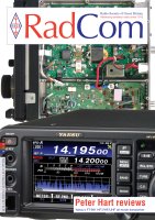
PHOTO 1
: A typical 3 band end fed portable
antenna of the type described.
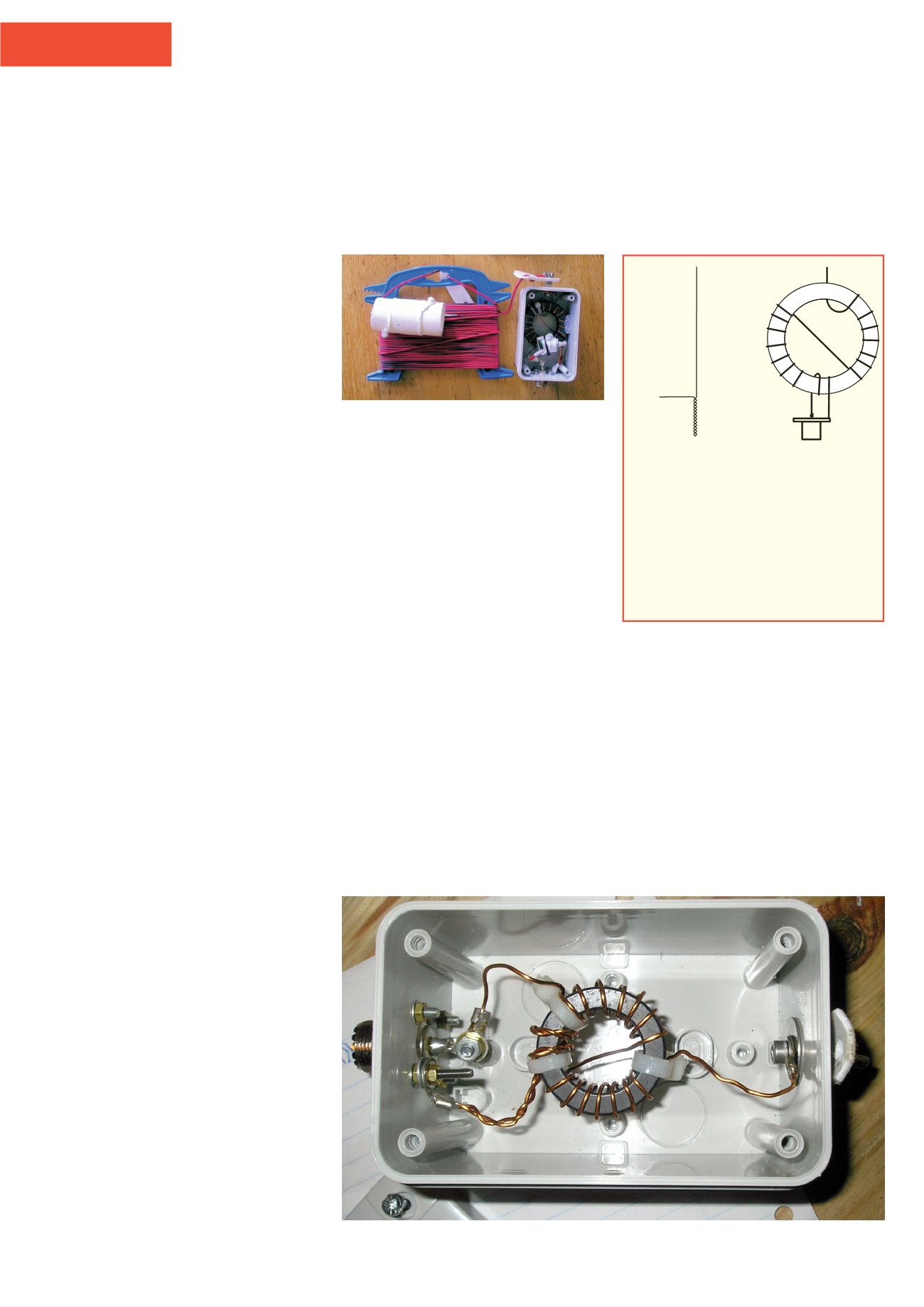
FIGURE 1:
Unun construction details. For
multi band use place a high voltage, high
current rated capacitor of 100-150pF
between points A and B. A FT140-43 toroid
is suitable for up to 50W – see text for
winding details.
PHOTO 2:
Prototype unun for 80m and 40m. A capacitor is additionally required to increase
coverage to include the higher bands.