


 55 / 100

Technical
So, starting myself
Fairly quickly I found how to wind the
autotransformer for the unun that takes care
of the transformation from a very high Z
in the feeding point of the end-fed 5 band
antenna, and very fast I found the values of
the shortening coils for both the 5 band and
3 band end-fed antenna.
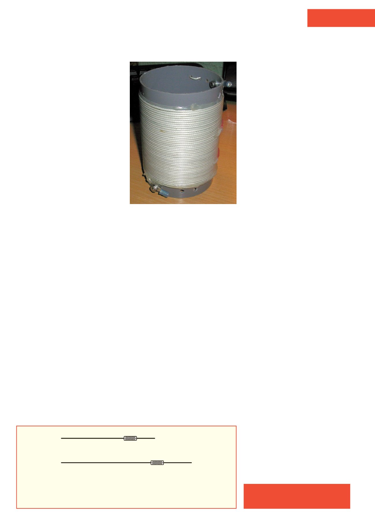
Figure 1
shows the
critical information for constructing the unun,
while
Figure 2
illustrates the element lengths
and coil details.
My first try
For Johan, ON5AH I made the first prototype,
just winding the transformer on a single
FT140-43 core (I had several lying around).
I bought a little ABS box at our local electrics
hardware store and though it was a bit too
large it did the job well enough.
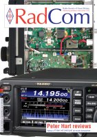
Photo 2
shows the completed unun in its box.
The unun is simply wound and secured with
cable ties. I used solder lugs and little bolts to
make life easier if I had to change anything. As
I only needed to use 80 and 40 metres I left
out the capacitor that would be required for the
higher bands. However, without a capacitor
the transformer only needed 2 + 6 + 6 = 14
windings instead of the 16 windings for the
multiband versions with a capacitor.
Next, I started building the inductor that
would shorten the antenna to 23 metres total
length. I calculated the necessary inductance
as 110µH using
MMANA-GAL
. I used pieces
of left over copper wire that I found in my junk
box. I stopped at 105µH, checked with my LC
meter, because that was the length of wire I
had handy. I would have had to put in another
solder joint to reach 110µH. 46 turns were
wound on an 80mm PVC tube left over from a
home DIY project.
I stabilised the inductor windings with hot-
melt glue and added solder lugs, nuts and
bolts so I could connect both the antenna
wires to the inductor. The completed prototype
inductor is shown in
Photo 3
.
I used other 2.5mm square (AWG13)
copper braided wires for the antenna wires (of
course I also found these in the junk box). I
hung the antenna from my shack window on
the first floor to a lamp-post across the street.
I started with 21 metres of wire between the
unun and the inductor and with 4 metres of
wire after the 105µH inductor. I had to start
adjusting the long part of the antenna for 40m
first and then adjust the wire after the inductor.
In a little over an hour I had adjusted the right
length for a good SWR on the entire 40 metre
band (SWR <1.5:1) and a SWR across about
100kHz of 80 metres. I went to Belgium the
next weekend so I could give the antenna to
Johan, ON5AH so he could try it and see if it
would suit his needs.
That was the prototype. During testing and
adjusting I compared the antenna with my
other wire antenna and V-dipole and I was
intrigued that such a little stupid antenna didn’t
work badly at all. I also found out that on 80m I
would need more ferrite core because although
the single FT140-43 core could handle 50W it
got warm with 100W of carrier.
So the plan quickly was born to build a
second antenna, to see if I could build an
auto transformer on 2 stacked FT140-43
(still had several of those in the spare-part
department!). Or perhaps even use a single
FT240-43 and if I could get the antenna to
work on the 5 bands it could work, 80, 40,
20, (15) and 10 metres. I already knew that
it was necessary to use a small tuner for 15m
because even the producer of the commercial
product stated this in his website. This second
antenna also would be a very handy holiday or
field day antenna.
Version 2
I starting building the unun and used a similar
case to the first antenna. I used two stacked
FT140-43 cores for the transformer. I used a
68pF 6kV capacitor (a bit on the bulky side,
but I had them in the junk box and you work
with what you have, not with what you would
like
to have). I hot-glued the windings to the
cores and glued the transformer to the bottom
of the cabinet to get good mechanical stability.
After adjusting the antenna length, I found
that it needed more capacitance to lower the
SWR on the higher bands, so I just soldered
an 80pF 10kV in parallel with the 68pF cap. It
didn’t look neat, but the now-150pF did the job.
After placing the second capacitor I
needed to readjust the antenna length again
(it became a bit shorter at the first 20 metre
long section) and SWR was good enough and
about the same as the commercially-produced
antennas.
I had to build a second inductor, for my
antenna, but as I ran out of junk wire I bought
10m of 0.75mm square (AWG 18) twin lead
and tore the wires apart. I wound another coil
on the same grey PVC pipe (the sort normally
attached to guttering at your home to get rid of
the rainwater). This also came out at 105µH.
Fixation was done in a similar way as before
with hot glue, solder lugs and 4mm stainless
steel nuts and bolts, to attach the antenna
wires to the inductor in the antenna itself.
I hung this antenna the same way as I did
with the first and started to get the 21 metre
part before the inductor set for 10, 20 and 40
metres by checking the SWR.
I shortened the wire so the SWR was
perfect on those bands.
Then I started cutting the 4 metre wire
after the inductor for the resonance point on
80 metres. After a bit fiddling I got the antenna
100% right.
I never give precise wire length for the
antennas and I will not give them now, though
in the schedule I found on the internet there
are precise lengths given. I do not work that
way because velocity factor for different wires
and insulation may vary up to 7% so it is
absolutely useless to give precise values, as
I do not know what type of wire or insulation
Jos van den Helm, PA1ZP
pa1zp1@gmail.comPHOTO 3:
Prototype 105µH coil, 45 turns on
80mm PVC pipe (see text).
10.1m
34µH 1.85m
40, 20 & 10m version
90 turns
20.35m
110µH 2.39m
260 turns
80, 40, 20, 15 & 10m version
FIGURE 2:
Construction of the two versions of the antenna. The coils are 1mm enamelled copper
wire close wound on 19mm diameter PVC tube. When tuning, start on the highest band and
adjust the length of the longer wire. The end marked C connects to point C of Figure 1. Note that
the wire lengths are for guidance only: the text contains details of how to ‘cut-and-try’.
February 2016
55