


 58 / 100

February 2016
58
Technical
you are going to use. The lengths in Figure 2
should be regarded as a guide.
Trimming the antenna for 40m and up is
straightforward but the 80m side must be done
in quite short increments because of the effect
of the inductor. There is nothing magic about
the value of the inductor – small variations
(±10%) just mean that the shorter wire will
be a different length and the bandwidth may
be slightly different.
For fun I simulated the antenna in
MMANA
with the shortening inductor. I found out that
the Q-factor is a very important aspect in
performance so make sure that the Q-factor
of the inductor is high enough, by using good
copper wires and a not-too-small diameter coil
form and a not-too-long inductor.
The performance and radiation patterns
are always formed by an antenna’s placing
and environment. This shortened 5 band
antenna works on 80 metres with about 3dB
loss against a full size dipole, and with reduced
bandwidth in SWR. On 40 metres performance
is the same as with a full size dipole – and that
is the same case on 20, 15 and 10 metres,
though you get a rather strange radiation
pattern with a lot of lobes because of the fairly
long antenna length.
SWR measurements with my 23m long 5
band end-fed were as follows:
• On 80m, SWR is unity on 3590kHz, but it
can be put on any frequency in this band
and you can use 50kHz down or up from the
centre frequency before you reach the 1.5:1
SWR points. It can be used without an ATU
in a 100kHz window. My rig’s automatic
ATU had no troubles at all in tuning the
whole 80 metre band.
• On 40m, SWR is 1:1 on 7090kHz with
me and the SWR 1.5 points are outside the
40m band, so the antenna can be used over
the whole of 40m without a tuner.
• On 20m, SWR is 1:1 at 14.150MHz and
the 1.5:1 SWR points are outside of the
band so again no tuner is required.
• On 15m, my antenna is best at 21.65MHz
with an SWR of 1.2:1, rising to 1.7:1 at
21.450MHz and 3:1 at 21.000, so you will
need an antenna tuner. The automatic tuner
built into most modern rigs will do the job.
• On 10 metres, SWR was 1:1 at 27.900MHz
and the antenna’s SWR 1.5:1 point was at
28.750MHz, so I could use the most-used
part of 10m in SSB and CW without any
antenna tuner. If you shorten the longer
piece of the antenna wire you could have a
greater part of 10 metres, but that will make
15m worse and will put best SWR points in
20 and 40 metres a bit higher in frequency.
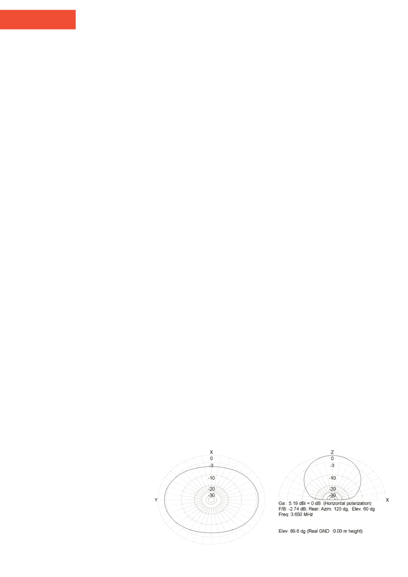
Simulations
I made a few plots of the radiation patterns of
the 23m long 5 band antenna in
MMANA-
GAL
. All radiation patterns are generated
over average ground and with the antenna
horizontally placed at 8 metres height at both
feed point and the end. These are shown in
Figures 3, 4, 5, 6
and
7
show the simulated
performance on the bands from 80 to 10m.
These figures are with the end-fed using a
105µH shortening coil, but without feed line
loss and transformer loss, so you may want to
adjust the figures lower by about 1dB to allow
for the unun and some cable loss.
A longer antenna for 80 and 40 if
you have more room
I had a 5 band antenna but my garden was able
to accommodate 9m more wire, so I rebuilt the
5 bander to a dual band end-fed for 80 and
40m. The 105µH inductor was replaced by
a 24µH inductor and the length of the wire
between the feedpoint and the inductor was
increased to about 23m (about 75 feet).
The wire after the 24µH inductor became
a bit over 8m (26 feet). Total length was now
about 31m (about 100 feet). The changes
made the antenna work much better at
80m, including increasing the 1.5:1 VSWR
bandwidth to about 180kHz. Bandwidth in
40m was unchanged and performance was
just a bit better (but not much).
The fun part was that the SWR in all bands
from 10-30m was below 3:1 and the tuner
built in to my TS-590S could now match the
antenna on all bands from 80-6m very easily.
This was not the intention of this antenna at all
but just a coincidence that happened. I have
used this antenna at home now for about two
years with great fun and satisfaction.
A trapped version for 80 and 40m
I built a trapped version for 80 and 40m.
The performance was about the same as the
32m long version with the 24µH inductor,
so it is rather useless to build one with a trap
because a trap is far more difficult to build as
a simple 24µH inductor, although the antenna
performed flawlessly on 80 and 40m. The trap
inductor was built on a 40mm PE pipe with
enamelled copper wire and an 80pF 2kV large
high current capacitor inside the PE tube. Of
course, all materials were found in my junk box
so it was just the idea, I had to try it.
This antenna was about 34m long,
comprising about 20m between the feedpoint
and 7.1MHz trap and another 14m of wire
after the trap.
A 4 band version 20.3m long
This 4 band version, using only about 20.3
meters of wire and without any inductor, can
be used in the same way as the 5 band version
on 15 metres with a tuner. Bandwidth of this
version on 40m is enough for the entire band
without tuner. Performance on 40m is about
the same as a full size 40m dipole. The 3-band
version with a 35µH inductor and the 12m
length has about 100kHz bandwidth in 40m
and about 3dB less performance than the 20m
long 4-band version.
Higher power considerations
Higher power versions can be made using a
FT240-43 core for the transformer, capable of
withstanding up to 250W PEP on 80m and
400W PEP on 40m and above.
Two stacked FT140-43 cores are good for
200W PEP on 80m and 300W PEP on the
higher bands. Winding the FT240-43 is done
in the same way as a single FT140-43 or
two stacked FT140-43. I always used 1mm
enamelled copper wires to wind the auto
transformer (unun) on the cores. Do not forget
to scratch of the enamel at the ends before
trying to solder this wire!
Good ideas
If you are going for the multi-band version (3,
4 or 5 bands), only start adjusting wire length
with the capacitor in place, otherwise you
will have to readjust again after placing the
capacitor.
It is a good idea to use a 1:1 current balun
with this antenna. The best place for this is
about 3m from the feedpoint of the antenna,
so common-mode currents will be reduced. It’s
FIGURE 3:
End-fed simulated performance on 80m.