


 38 / 100

February 2016
38
Review
filter and a band stop filter to reduce harmonics.
Using a spectrum analyser but no
fundamental notch filter, and carefully
controlling the fundamental level to the analyser,
I confirmed these figures up to 24GHz.
Power meter accuracy
The manual clearly states that the front
panel power meter is for indication only and
external power metering is advised,
but I thought it would be interesting
to see how accurate the review
model was. The results are shown
in
Table 3
.
The test model measured
within <1dB of my power meter.
Considering the difficulty of
accurately reading a meter without
a parallax mirror, quite frankly, this
is at least as good as some cheap
amateur power meters I could
mention.
Insertion loss on receive
I measured the ‘straight through’
receive insertion loss of the Gemini
23 as less than 0.5dB, but this
figure is not significant and is likely
to be much less than the overall
feeder loss. Also, as it is advisable to
use a masthead preamp to overcome
cable losses at 23cm the through
loss of the amplifier in that case is
irrelevant.
Thermal protection test
To check the thermal cut out and the
suitability of the amplifier for 1 minute on,
1 minute off modes such as WSJT, I ran
the amplifier ‘key down’ at a conservative
150W CW output in an ambient of 24°C,
with adequate fan clearance. The amplifier
ran for 1 minute 40 seconds before the
thermal cutout tripped. After 30 seconds of
key up, I repeated the test and got a very
similar time before the trip cut out again.
Conclusions
The Gemini 23 is a very well designed,
neat and compact amplifier that, unlike
many lower cost kits and pallet amplifiers
is a ‘plug and play’ unit with a PSU, has
a well designed harmonic filter and built
in protection circuitry, making it easy to
integrate in to a 1296MHz system for both
terrestrial and EME use. The power output
is such that even with a single long Yagi or
small dish, EME contacts can be made with
larger stations, and it will perform well in
a terrestrial situation for aircraft scatter and
long distance tropo contacts.
Care needs to be taken with this sort
of power level at 1296MHz, both from a
personal safety (non-ionising radiation)
point of view and with the types of cables,
relays and antennas used. Check the
manufacturer’s specifications, especially
for the isolation of relays that are used to
protect preamplifiers. The Gemini 23 has
been well designed to minimise radiation
from the case, but good practice should be
observed on siting antennas to make sure
they do not radiate close to persons.
Test equipment used in this review
All measurements in this review were
made using, surplus, ‘good amateur radio
standard’ test equipment that does not
necessarily carry a current professional
calibration certificate, so measurements
should be taken as a guide only. The
equipment employed was:
• HP436A RF power meter with 8484A
diode power sensor
• Narda 76910 10dB power attenuator
• Assorted attenuators
• HP11691D directional coupler (checked
at 1296MHz)
• HP 8592B spectrum analyser
• Marconi 2024 RF signal generator
WEBSEARCH
[1] Linear Amp UK –
www.linamp.co.uk/products.html
[2] The DX Shop –
www.thedxshop.com/linear-amp-uk-linear-amplifiers.html
[3] ETSI Specification EN 301 7831 v 1.21 –
http://bit.ly/1iA9pLM[4] W6PQL control board –
www.w6pql.com/amplifier_control_board.htm
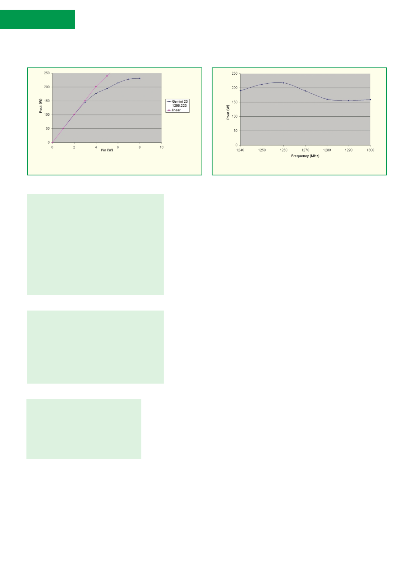
FIGURE 1:
Power out vs power in compression curve for the Gemini 23.
FIGURE 2:
Frequency response of the Gemini 23 at 3W drive.
TABLE 1: Power output vs drive power.
Drive Measured Linear output Deviation from
(W) output (W) power * (W) linear power (dB)
1
50.7
50.7
0.0
2 101.2
101.2
0.0
3 145.2
151.4
-0.2
4 177.0
201.8
-0.6
5 194.5
239.9
-0.9
6 214.8
285.1
-1.2
7 228.6
338.8
-1.7
8 231.7
402.7
-2.4
* Note that the amplifier does not produce the power
in this column, it is just a linear interpolation of the
straight part of the curve in Figure 1.
TABLE 2: Frequency response at 3W drive.
Frequency Output
Deviation from
(MHz)
power (W)
max power (dB)
1240
190.1
-0.6
1250
212.3
-0.1
1260
217.3
0
1270
189.2
-0.6
1280
160.3
-1.3
1290
155.2
-1.5
1300
159.2
-1.3
TABLE 3: Front panel power
meter accuracy.
Meter (W)
Actual (W)
Error (dB)
25
29.5
0.7
50
62.1
0.9
150
125.3
-0.8
200
248.3
0.9