


 34 / 100

February 2016
34
Technical
Standard components are used throughout.
The 220pF capacitors are polystyrene types,
although good quality ceramic or mica
types would make a good substitute. Other
capacitors are disc ceramic. Resistors are
0.25W or 0.125W. One top corner of the
crystal was scraped clean and tinned so that it
could be soldered to the copper for mechanical
stability. The DC supply is stabilised by a 7.5V
Zener diode.
The circuit is arranged so that the output
MPSH10
560Ω
220p
220p
10k
10k
0 1
0 1
47Ω
ZD
7V5
330Ω
0 1
+12-14V DC
2n2 FT
FB
10MHz
33p
47Ω
470p
1k2
27Ω
100Ω 100Ω
Output
-30dBm
PHOTO 4:
Close-up of the assembled board. Note
ground connections soldered to the ground plane.
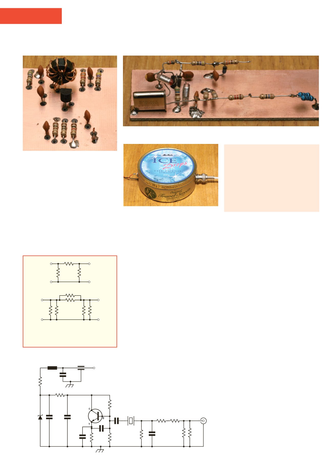
PHOTO 5:
The prototype 10MHz oscillator.
PHOTO 6:
A metal sweet tin provides excellent
electrical screening for the 10MHz oscillator.
is taken via the crystal. This greatly reduces
harmonic output and also filters out broadband
noise from the oscillator and its power supply.
The shunt capacitor and resistor values of 47Ω
and 470pF were chosen for an output voltage
of exactly 1Vpp (0.5Vp or 0.353V RMS) as
measured with a calibrated oscilloscope. The
final output is reduced to 7.07mV RMS (10mV
peak) using a resistive attenuator. Output
voltage is only accurate when terminated by
an external 50Ω load.
Testing
The oscillator worked very well with very little
effort required to achieve the required 1Vpp. I
used a 220Ω pot for initial output adjustment.
Once the correct level was achieved, this was
replaced by a fixed 47Ω resistor. Don’t depend
on the accuracy of the output level unless it has
been checked against a well calibrated meter
or scope. Output level may be dependent on
crystal Q or the characteristics of individual
transistors.
R2
R1
R3
100Ω 2k7
560Ω
82Ω
100Ω 2k7
-10dB
FIGURE 3:
(Top) general arrangement of a pi
attenuator. (Bottom) values for a practical
-10dB pi attenuator for 50Ω systems.
FIGURE 4:
RF signal source.
Screening
A weak signal source is only useful if you can
be sure you are measuring the output signal
and not leakage from the oscillator or its power
supply wiring.
Amateur radio gear has been built in
various enclosures. Tuna or sardine tins were
once popular homes for QRP transmitters.
The tobacco tin was once the most popular
enclosure for circuits that needed extensive
screening. As tobacco now comes in pouches
and I don’t smoke anyway, I decided to mount
the oscillator in sweet tin. The unscreened
oscillator produced a very strong 10MHz
signal in my shack receiver. Simply placing
the oscillator in the tin and taking the output
from a BNC socket reduced the signal from
S9 to barely audible. Taking the 13.8V DC
into the enclosure via a 2.2nF bolt-in feed-
through capacitor reduced the leakage down
to the receiver noise floor. I then took a few
metres of insulated wire and used it as an
aerial to find any leakage. The only leakage
I could find was at the outer terminal of the
feed-through capacitor. When my makeshift
aerial was connected to this point, I could hear
a faint signal in the shack receiver. This was
eliminated by soldering a 100nF capacitor
from the feed-through capacitor to the inside
of the can and placing a ferrite sleeve (Maplin
N97AB or similar) on the short DC supply
wire to the oscillator. These components are
included at the top-left of the schematic.
The ‘enclosure’ is shown in
Photo 6
. I had
intended to solder the lid on the tin, but this
seems unnecessary as there is no measurable
leakage from the finished project.
TABLE 1: Suggested resistor values
for different 50Ω attenuators.
Attenuation
R1/R3
R2
3dB
292Ω
17.6Ω
6dB
150Ω
37.3Ω
10dB
96.2Ω
71.2Ω
20dB
61.1Ω
247Ω
30dB
53.3Ω
790Ω
40dB
51Ω
2500Ω