


 31 / 100

February 2016
31
Regulars
be added around the edges of the washers
and nuts to help weatherproof the fixings.
A dipole leg is slid into its short length of
tube until it reaches the ABS box, then a hole
is drilled through the two tubes and the dipole
leg fixed in place using a nut and bolt passed
through the hole to finish the assembly off.
Inside the ABS box a connection plate is
added made up from single-sided PCB with
a 10mm strip etched down the centre. The
connection plate has two holes drilled in
the copper sections that match up with the
two bolts protruding from where the dipole
assembly is attached. The connection plate
is fastened to these bolts using nuts and
washers forming the connection with the
dipole.
A hole drilled in the lower wall of the ABS
box enables the feeder cable (coaxial cable
in this case) to be passed through with its
conductors soldered to the connection plate
(note that a balun was added later and is not
shown here for clarity). A cable tie is used
to hold the feeder cable in place and then
sealant run around the feeder cable where it
enters the box to waterproof the arrangement.
A small length of insulation tape should be
attached to indicate the dipole leg connected
to the inner conductor of the feeder cable for
reference, as seen in Photo 5.
To attach the dipole centre to a mast, two
saddle-clamps are bolted to the ABS box as
can be seen in Photo 6. The ABS box’s lid
is attached by first adding sealant around
its edge and then held in place using self-
tapping screws.
Another suggestion for a dipole centre
made up using a three-way 20mm electrical
circular conduit box is shown in
Photo 7
.
The diameter of the aluminium tube used to
make the dipole is usually smaller than the
box’s 20mm diameter holes and these holes
are reduced using short lengths of 20mm
conduit with additional lengths of conduit slid
inside after a slot was cut laterally to allow the
conduit to be a snug fit.
The dipole was made up using two
aluminium tubes with a short length of
plastic rod inserted in between them and
glued in place (using epoxy glue) to leave a
10mm gap. The dipole is passed through the
reduced holes in the three-way circular box
with self-tapping screws and epoxy glue used
to hold it centrally in place. The self-tapping
screws will absorb a small amount of RF
energy and dissipate this as heat when the
dipole is transmitting a signal, however for RF
powers up to 150W or so, this heating effect
is not a significant problem (unlike if several
megawatts were being transmitted).
Two holes are drilled in the base of the
electrical conduit circular box to enable it to
be fixed to the antenna’s boom using nuts
and bolts.
In a similar manner to the previous design,
a connection plate is added to the dipole
made up from single-sided PCB with a 10mm
strip etched down the centre. Two brass
terminals (from a ‘chocolate block’ connector)
are soldered to the connection plate, then
two holes drilled in the connection plate’s
copper sections to allow it to be attached to
the dipole using self-tapping screws.
To provide a waterproof seal for the coaxial
cable, a 20mm diameter screw-tight gland is
glued using epoxy glue to the conduit box’s
third hole. The coaxial feeder cable is passed
through and the gland tightened to make
the seal. The coaxial cable’s conductors
are attached to the dipole using the brass
terminals by tightening the screws (note that,
again, a balun was added later and is not
shown here for clarity).
Three-way 20mm electrical circular
conduit boxes also come with a lid, a gasket
and screws, making weatherproofing of the
arrangement fairly straightforward.
Conclusion
Making up your own dipole centre can be
an interesting exercise and I hope these
suggestions have provided something to
ponder over.
REFERENCE
[1]
Radio Communication Handbook, 5th edition
,
Section 12, HF Aerials, page 12.58
Mike Parkin, G0JMI
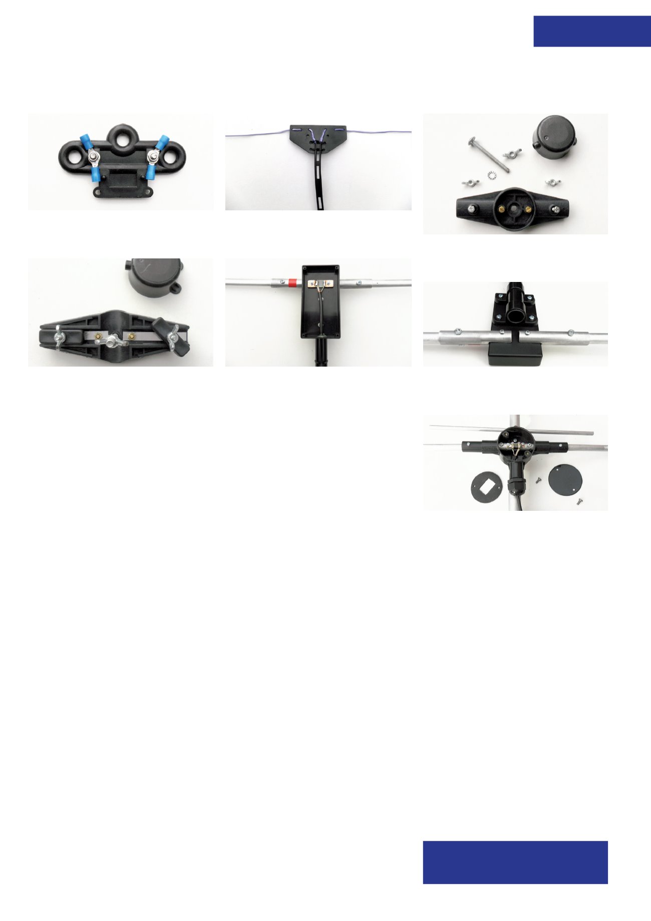
email2mikeparkin@gmail.comPHOTO 1:
A typical dog-bone dipole centre used
for wire antennas.
PHOTO 2:
A wire dipole centre made from 3mm
uPVC plastic.
PHOTO 3:
A typical dipole centre used for beam
antennas.
PHOTO 4
: Typical dipole centre clamping
arrangements used for beam antennas.
PHOTO 5:
A dipole centre made using an ABS
box and aluminium tubing.
PHOTO 6:
Underside of the dipole centre made
using an ABS box and aluminium tubing.
PHOTO 7:
Dipole centre made from a 3-way
electrical 20mm conduit box.