


 37 / 100

re-enabling the PTT once the heatsink
temperature drops to an acceptable level.
Out of the box
The Gemini 23 comes well packed and includes
a user’s manual with a circuit of the RF board.
A standard IEC mains lead is supplied along
with a set of spare internal and external fuses,
a phono plug for PTT and a 6 pin mini DIN
plug for the accessory socket (
Photo 1
). Be
really careful when soldering to this plug as it is
very small and the plastic body is easily melted
if you overheat the pins. My preference when
faced with needing a plug for one of these mini
DIN sockets is to buy a cheap 6 pin DIN PS/2
keyboard or mouse extension lead from eBay.
I then cut off the female connector and throw
it away, so I don’t have to solder a plug on!
The user’s manual contains a detailed circuit
description with much useful information
about the design philosophy.
The front panel is simple and clear (
Photo
2
) with switches for power, standby mode
and preamp control. Note that the ‘preamp’
switch does not imply a built in preamp: it is to
control and external masthead unit. There are
LED indicators for overdrive, over temperature,
SWR fail and TX on, and an analogue meter
indicating power, calibrated in watts. The rear
panel (
Photo 3
) has N type connections for
antenna and transceiver input, an IEC mains
connector, a 5A mains fuse, a phono socket
for PTT control and a 6 pin mini DIN accessory
port.
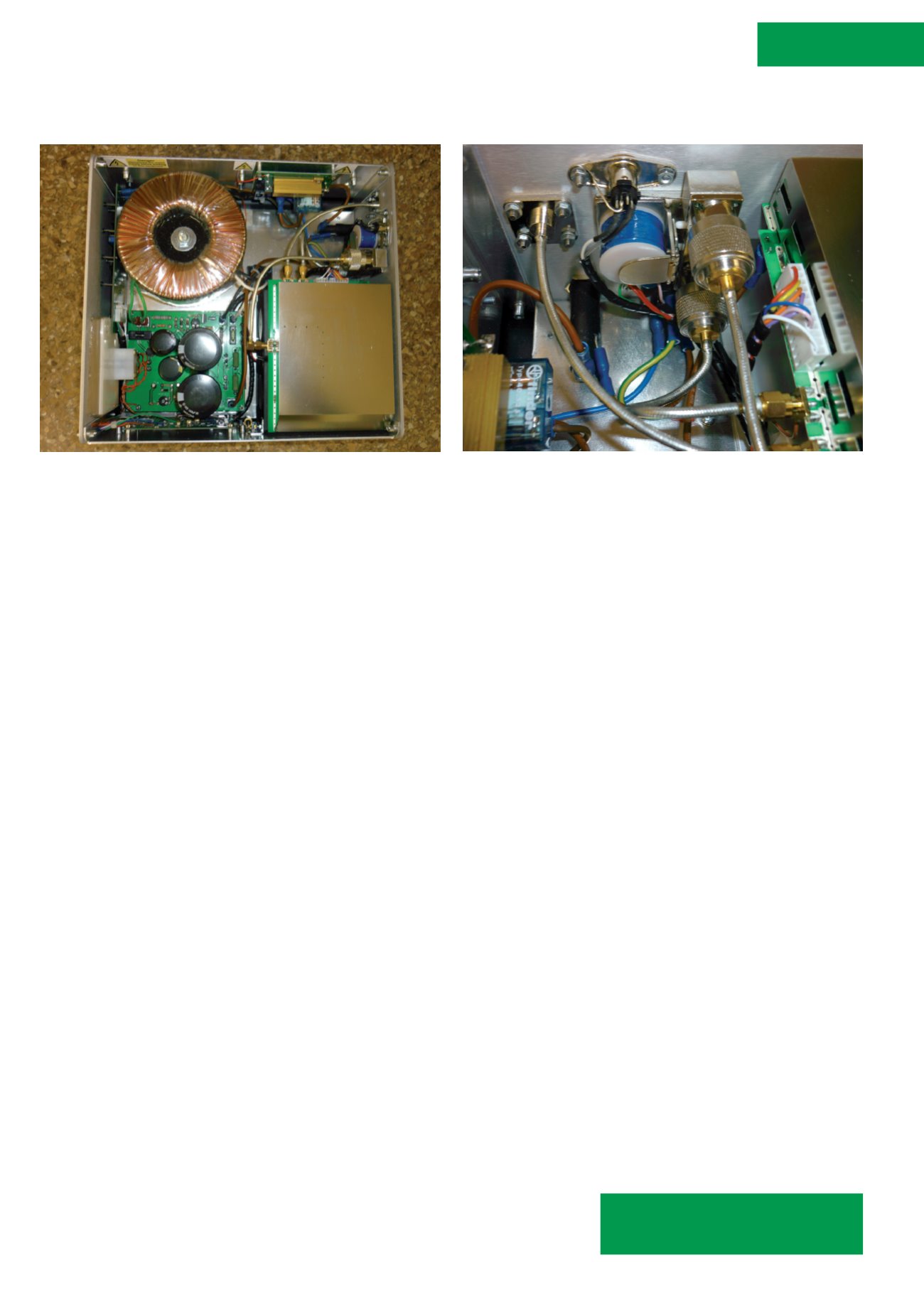
Design and construction
The inside of the Gemini 23 is shown in
Photo
4
. The amplifier looks very well made and the
use of an RF-quiet linear power supply with
a heavy toroidal transformer will please users
who operate on the lower bands as well as
23cm. The RF module uses a rugged dual
LDMOS FET, the NXP BLFG13L-250, operated
in an unbalanced (parallel) configuration with
a combination of a 9 element low pass filter
and a band stop filter to reduce harmonics.
The output changeover relay is a well-known
Tohtsu model, well capable of handling the
output power (
Photo 5
). I was initially a little
surprised when I saw this relay as its isolation
at 1296MHz is known in the GHz bands
fraternity as not really being adequate to protect
a preamp when used in a masthead circuit. I
took this up with the designer, but he pointed
out – quite rightly – that in the Gemini 23 it
is simply used to switch the amplifier in and
out of circuit, not to isolate a preamp. He also
added that using a ‘professional’ relay with
high isolation would have added some £500
to the retail price of the amplifier!
RF interconnections are all made using
semi-rigid coax and either SMA or N type
connectors to minimise leakage and provide
low loss. A correctly torqued SMA connector
will easily handle the amplifier’s rated output
power, but expect some temperature rise in
both the cables and connectors due to losses.
Control and monitoring of the Gemini 23
is provided by the well-known and widely
used ‘W6PQL board’
[4]
. The designer of the
board describes this as “the Swiss Army knife”
of control boards due to its high functionality.
In the Gemini 23 it is used for forward and
reverse power protection, fan control and
thermal monitoring and protection.
Linearity
Linearity can be measured by inserting two
closely-spaced RF carriers in to the amplifier
and measuring the amount of 3rd order
intermodulation on the output. This can be
done by resistively combining two RF carriers
or using an SSB transmitter with two tone
modulation. Due to the difficulty in getting
a very linear 8 watt RF source at 1296MHz
(and the fact that I only have one decent
signal generator!) I did not perform a two
tone intermodulation test on the amplifier.
Some measure of linearity can be made by
measuring the amplifier’s output power versus
input power curve and measuring the 1dB
compression point P1dB. The higher the P1
dB the more linear the amplifier, so I decided to
perform this test instead.
Table 1
and
Figure 1
show the results,
with saturated CW power of the amplifier at
around 240W and a P1dB of around 200W.
This compares well with the manufacturer’s
specification of 180W PEP and 210W
saturated and indicates that the amplifier is
very linear up to the 180W PEP level. The
manufacturers claim P1dB of 180W and 3rd
order intermodulation products of -30dBc at
180W PEP. My measurement of P1dB seems
to confirm the claims.
Frequency response
The amplifier was driven with a constant 3W
and the input frequency moved in 10MHz
steps from 1240 to 1300MHz.
Table 2
shows
the results and it can be seen that the amplifier
is flat to 1.5dB over the whole band at this
power level. Maximum gain and output was
at 1260MHz.
Harmonic levels
The manufacturer of the amplifier claims
extremely good harmonic and spurious
suppression, up to 6th order, of >70dB at
200W. This is achieved by using a highly
effective combination of a 9 element low pass
PHOTO 5:
The antenna changeover relay and RF interconnections.
PHOTO 4:
Inside view.
February 2016
37
Review
Dr John Worsnop, G4BAO
john@g4bao.com