


 41 / 100

Technical
February 2016
41
having a steel inner conductor such as
RG6, are spaced 20cm (8’’) and tensioned
with a simple 10kg weight. Wire spacing
was determined experimentally to present
a 50Ω feed resistance after tuning out
reactance with a series capacitor. Thicker
or a greater quantity of shunt wires would
increase the bandwidth of the radiator but,
as with most wire GPs, the bandwidth is
also restricted by that of the radials.
Current on the feeder braid, and
indirectly on the lower part of the mast, was
monitored via a transformer of 20 turns on
a T200-2 iron dust ring. This fitted over
the coax connector and was temporarily
located just below the connection
between braid and mast. A 47Ω load was
connected across the transformer and
OA47 diode added, to feed a DC Voltmeter.
The capacitor was first adjusted for lowest
SWR with a few watts of input. The
antenna then responded, as predicted by
an
EZNEC
model, with a reassuring deep
null in feeder braid current as the inductor
was adjusted. This adjustment is vital
for correct operation of the counterpoise
because it indicates when the braid of the
feeder is closest to ground potential. The
capacitor was now trimmed with the result
that 100pF of capacitance gave unity SWR
for the radiating part at 3.75MHz (where
the tests were made). SWR did not change
significantly between radial systems once
they were tuned. To cover the whole 80m
band down to 3.5MHz with either radial
system required a tuning capacitor of
maximum 250pF and some additional
PLR loading inductance. Field strengths for
the different radial systems were compared
within a few hours, to minimise the effect
of any change of ground moisture, and are
reported in
Table 1
.
The antenna with 0.11
λ
PLR produced
signal reports within 1dB of those obtained
when using a 24m (80’) mast with 120
half wave
buried radials. I remain sceptical
of the relative field strength figures, which
are probably within the tolerance of my
measurements, limited by the accuracy
with which I could maintain input power
and adjust an attenuator to maintain a
constant reading at the radio’s S-meter.
However, the logical conclusion is that a
relatively small resonant PLR system can,
except for restricted bandwidth, perform
as effectively as an extensive buried
radial system. It is also apparent that the
traditional 4x
λ
/4 radial system offers no
radiation advantage over a smaller PLR
whilst occupying an unnecessarily large
footprint.
Other applications
Several frequency bands, within a
frequency ratio up to 5:1, may be covered
with a single PLR system by selecting
different values of loading inductance
for each band and using, for example, a
loaded radiator that is
λ
/8 at the lowest
frequency in association with a PLR that
has 0.2
λ
side at the highest frequency.
A PLR may be used to reduce the
space required for the lower band radials
of popular trapped multiband vertical
antennas. Conventional radials for higher
bands, rigged between the PLR wires, may
still be connected to the coax braid, in
parallel with the PLR inductor.
At phased arrays, such as 4 squares,
the element spacing is usually
λ
/4 or less.
This creates difficulty when placing sets of
elevated
λ
/4 radials where they will have
minimum mutual interaction. PLR systems
can overcome this problem.
A PLR may be used as a counterpoise,
as an alternative to a buried ground system,
beneath existing horizontal doublets or
inverted L antennas, against which the
vertical feeder or vertical wire may be
driven.
A grounded tower, top loaded by an
HF beam, may be shunt driven against a
PLR of say 20m side to make an efficient
antenna for the 1.8MHz band.
A
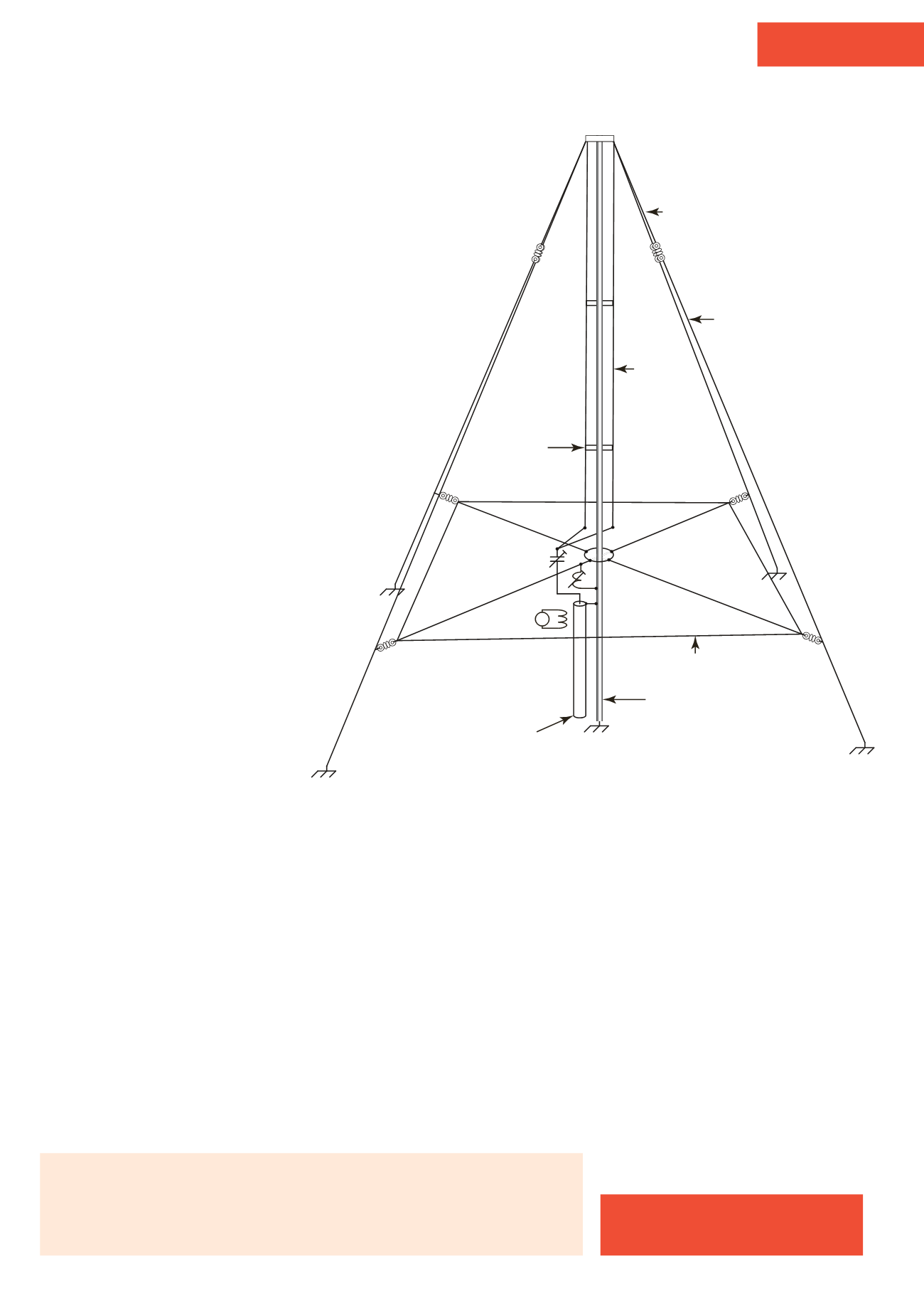
Metal pole
Wire
50Ω
Insulating
spacers
Wire
Wire
Rope
FIGURE 1:
The experimental perimeter loaded radial antenna.
Tony Preedy, G3LNP
g3lnp@talktalk.netTABLE 1: Experimental results.
System
Relative field
Load µH Wire
2:1 bandwidth
Area m2/%
4x
λ
/4
0dB
0
83m 100kHz
882/100
0.15
λ
PLR +1dB
2
83m 112kHz
144/16.3
0.11
λ
PLR + 0.5dB
3
62.4m 82kHz
83/9.4