


 46 / 100

February 2016
46
A
fter reading December’s
issue
Peter
Martinez,
G3PLX took issue with
my simplistic description of the
ClickLock
technique. He sent
this much more comprehensive
description of how it can be used
to take out all timing and frequency
unknowns
in
any
receiver,
operating from LF to HF.
Peter says: “I would like to clarify Andy’s
reference to my
Clicklock
technique saying
that the idea was to inject the 1 pulse per
second (PPS) pulse from a GPS receiver ‘…
into and on top of the audio from the receiver
in order to overcome the poor stability of the
soundcard’. This isn’t what I was doing.
“The 1 PPS from the GPS goes into the
ANTENNA input to the receiver along with
the weak signal to be detected. The usual
GPS PPS pulse is a narrow pulse of about 5
volts amplitude with fast rise and fall edges.
A capacitor/diode/resistor network separates
out the rising edge and results in a click in the
receiver every 1 second. It’s very strong on
the lower bands and may need attenuating
but can be heard right up to 30MHz in some
situations.
“The receiver is a conventional SSB
receiver feeding its audio to a soundcard and
thence to the software. The first task of this
software is to identify the 1 PPS pulse. If the
soundcard sample rate was, for example,
exactly 12kHz, this could be done by feeding
the audio samples into a 12,000-long data
array and finding the one location with the
largest signal, but inevitably the PPS pulse
will drift relative to the soundcard sample
stream. This is overcome by re-timing the
audio sample stream at a new rate, and
locking this secondary sample rate so that
the 1 PPS pulse does not drift relative to it.
This retimed rate is thus EXACTLY 12kHz
regardless of how far off the soundcard
sample rate might be. The downstream
software is then processing the data as if it
was coming from a virtual soundcard with a
GPS-locked sample rate.
“This is what Andy was describing in his
column, but this is trivial compared to the
really clever bit, which I will now describe.
Not only can the 1 PPS pulse provide the
timing reference for the soundcard, but
by feeding it into the antenna rather than
into the soundcard, it can do the job of a
frequency-standard at the receiver input
frequency. Let’s suppose the receiver IF
bandwidth is a few hundred Hz and the BFO
pitch is set to deliver the received signal to
the audio output centred on 1000Hz. At this
point the 1 PPS click will look like a burst of
sine wave at 1000Hz repeating at 1 second
intervals. If the receiver is off-frequency, the
phase of these sine waves will drift relative
to the 1Hz pulse envelope. These 1000Hz
bursts are fed into I and Q multipliers with
1000Hz sine / cosine reference waveforms.
The resulting demodulated baseband pulses
can then be fed to a phase discriminator to
form a phase correction signal. If this is fed
back to the 1000Hz reference waveform, the
resulting phase-lock loop will cancel the drift
of the PPS pulse sine wave relative to the
1Hz envelope. The I and Q outputs of the
multipliers can then be thought of as coming
from a virtual I/Q receiver, which is not only
locked in time to the GPS but locked in RF
phase. Further software can then process the
retimed / re-phased I and Q streams.
“In this way, an ordinary SSB receiver
can be pressed into service as a GPS-locked
coherent receiver for all manner of extremely
weak signal experiments. Several people
have taken this idea forward for their own
work.”
Peter than went on to describe a simple
alternative way of describing the technique
“I thought an expansion would help. There
Design Notes
Technical
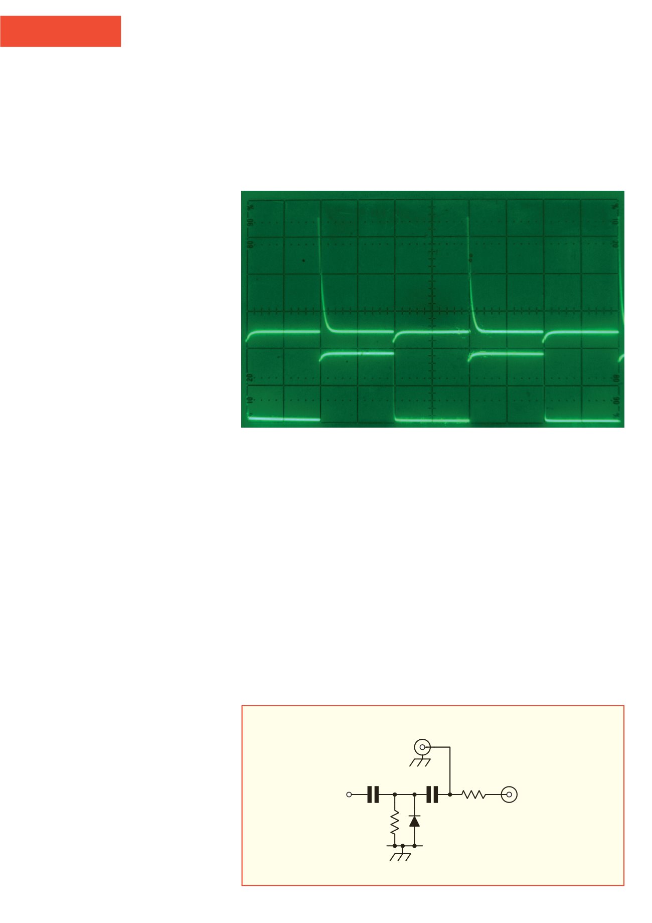
FIGURE 1:
Circuitry used to enhance the
leading edge of the 1 pulse per second
signal generated by a GPS receiver.
(*) = see text for notes on these values.
PHOTO 1:
The waveform generated by the circuit of Figure 1. For this illustration, the circuit was
driven from a 1kHz square wave rather than the 1 PPS signal from a GPS receiver.
1n
(*)
1k
1N5711
(*)
Output to
receiver
Antenna
input
1 PPS in
from GPS
receiver